Product Description
Ball Screw with Nut details
Ball screw is made of screw, nut and ball. The function is to turn the rotary motion into liner motion, which is a further extension and development of ball screw. The significance of this development is to move into a rolling bearing from sliding action; With little friction, ball screws are widely used in various industrial equipment and precision instruments.
WHAT CAN WE SUPPLY?
-1.We have TBI or CHINAMFG sizes for your selection.
Our ball screws and nuts are the same sizes as TBI or CHINAMFG ,they can be interchanged with TBI or THK.
TBI sizes have enough inventory in stock.
CHINAMFG sizes are produced on request.
-2.We are able to machine the 2 end sides of ball screws according to your requirements.
-3.We have full range of products what can be matched with ball screws.
We are able to match for you completely, including Machined Ball screw, Ball screw Nut, Nut housing/Nut Bracket, Shaft Coupler, End support unit.
-4.We provide many different series of ball screws and screw nuts, like SFU,SFK,SFS,SFI,SFY,SFA,DFU,DFI series and so on.
| SFU Ball Screw Nut Model No.(plastic deflector or metal deflector ) |
| SFU1204-3;SFU1605-3;SFU1605-4; SFU1610-2; SFU2005-3;SFU2005-4;SFU2505-3;SFU2505-4;SFU2510-4;SFU3205-3; SFU3205-4;SFU4005-4;SFU4571-4; SFU5571-4;SFU6310-4;SFU8571-4 |
| SFK Ball Screw Model No. |
| SFK0601;SFK0801;SFK0802;SFK082.5;SFK1002;SFK1004;SFK1202;SFK1402 |
| SFS Ball Screw Model No. |
| SFS1205;SFS1210;SFS1605;SFS1610;SFS1616;SFS1620;SFS2571;SFS2510;SFS2525;SFS3210;SFS4571 |
| SFI Ball Screw Model No. |
| SFI1605;SFI1610;SFI2005;SFI2505;SFI2510;SFI3205;SFI3210;SFI4005;SFI4571 |
| SFE Ball Screw Model No. |
| SFE1616;SFE2571;SFE2525;SFE3232;SFE4040 |
| SFY Ball Screw Model No. |
| SFY1616;SFY2571;SFY2525;SFY3232;SFY4040 |
| SFA Ball Screw Model No. |
| SFA1610;SFA1620;SFA2571;SFA2510;SFA2525 |
| Ball Screw End Supports Model No. |
| BK10 BF10, BK12 BF12, BK15 BF15, BK17 BF17, BK20 BF20, BK25 BF25,BK30 BF30, BK35 BF35, BK40 BF40 |
| EK06 EF06, EK08 EF08, EK10 EF10, EK12 EF12, EK15 EF15, EK20 EF20; EK25 EF25 |
| FK06 FF6, FK08 FF08,FK10 FF10, FK12 FF12, FK15 FF15, FK20 FF20, FK25 FF25, FK30 FF30 |
| Ball Screw Nut Housings Model No. (Aluminium or Iron) |
| DSG12H(1204),DSG16H(1605/1610), DSG20H(2005/2571), DSG25H(2505/2510), DSG32H(3205/3210), DSG40H(4005/4571),DSG50H(5005/5571) |
Each series has its own characteristics. The following table list the differences in appearance and characteristics for your reference.
Rolled Ball Screw Application:
1. Engraving machines; 2. High speed CNC machinery;
4. Auto-machinery. 3. Semi-Conductor equipment;
5. Machine tools; 6. Industrial Machinery;
7. Printing machine; 8. Paper-processing machine;
9. Textiles machine; 10. Electronic machinery;
11. Transport machinery; 12. Robot etc.
Rolled ball screws can not only be used in above general machinery, but also in many advanced industries. Rolled ball screw with a motor assembles electrical-mechanical actuator, which is more eco-friendly than hydraulic pump system. Nowadays it’s applied to electric vehicles, solar power plants, railway devices and many medical and leisure equipments.
/* March 10, 2571 17:59:20 */!function(){function s(e,r){var a,o={};try{e&&e.split(“,”).forEach(function(e,t){e&&(a=e.match(/(.*?):(.*)$/))&&1
| Precision: | C7 |
|---|---|
| Screw Diameter: | 31-40mm |
| Flange: | Without Flange |
| Customization: |
Available
|
|
|---|
.shipping-cost-tm .tm-status-off{background: none;padding:0;color: #1470cc}
|
Shipping Cost:
Estimated freight per unit. |
about shipping cost and estimated delivery time. |
|---|
| Payment Method: |
|
|---|---|
|
Initial Payment Full Payment |
| Currency: | US$ |
|---|
| Return&refunds: | You can apply for a refund up to 30 days after receipt of the products. |
|---|
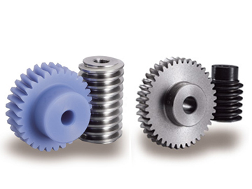
What maintenance is required for worm screw gear systems?
Maintaining worm screw gear systems is essential to ensure their smooth operation, longevity, and optimal performance. Here are the key maintenance tasks typically required for worm screw gear systems:
- Lubrication: Proper lubrication is crucial for reducing friction, wear, and heat generation in worm screw gear systems. Regularly monitor lubricant levels and follow the manufacturer’s recommendations for lubrication intervals and types of lubricants to use. Inspect lubricant quality and cleanliness, and replenish or replace the lubricant as needed. Pay attention to proper lubrication in both the worm screw and the worm wheel to ensure efficient torque transmission and minimize wear.
- Cleaning: Regularly clean the worm screw gear system to remove dirt, debris, and contaminants that can accumulate on the threads, teeth, and other contacting surfaces. Use appropriate cleaning methods and solvents recommended by the manufacturer. Ensure that the cleaning process does not damage the components or compromise the lubrication system.
- Inspection: Conduct routine inspections to identify any signs of wear, damage, or misalignment in the worm screw gear system. Check for excessive backlash, abnormal noise, vibration, or irregularities in operation. Inspect the teeth, threads, and other critical areas for signs of wear, pitting, or scoring. If any issues are detected, take appropriate measures to address them promptly, such as adjusting the backlash or replacing worn components.
- Alignment: Proper alignment is crucial for the optimal performance and longevity of worm screw gear systems. Periodically check and adjust the alignment of the worm screw and the worm wheel to ensure smooth and efficient meshing. Misalignment can result in increased friction, wear, and reduced performance. Follow the manufacturer’s guidelines for alignment procedures and use precision measurement tools as necessary.
- Load Distribution: Monitor the load distribution across the teeth of the worm wheel. Uneven load distribution can lead to premature wear and failure of the system. If necessary, adjust loads, redistribute the load by using multiple worm screws, or consider using additional supporting mechanisms to ensure uniform load distribution.
- Temperature Monitoring: Keep an eye on the operating temperature of the worm screw gear system. Excessive heat can indicate problems such as inadequate lubrication, overloading, or inefficiencies. Monitor temperature using appropriate sensors or thermal imaging techniques and take corrective actions if the temperature exceeds recommended limits.
- Periodic Overhaul: Depending on the application and usage conditions, consider scheduling periodic overhauls or maintenance intervals for the worm screw gear system. During these overhauls, disassemble the system, inspect components thoroughly, replace worn or damaged parts, reassemble with proper lubrication, and perform necessary adjustments. The frequency of overhauls will depend on factors such as operating conditions, loads, and manufacturer recommendations.
- Documentation: Maintain proper documentation of maintenance activities, including lubrication schedules, inspection records, repair or replacement history, and any troubleshooting performed. This documentation provides a valuable reference for future maintenance, helps identify recurring issues, and enables better tracking of the system’s performance over time.
It’s important to note that specific maintenance requirements may vary depending on the design, materials, operating conditions, and manufacturer recommendations for the worm screw gear system. Always refer to the manufacturer’s documentation and guidelines for the particular system being used, and consult with experts or maintenance professionals if needed.
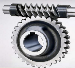
Can worm screws be customized for specific engineering needs?
Yes, worm screws can be customized to meet specific engineering needs and application requirements. Customization allows for tailoring the design, dimensions, materials, and other parameters of the worm screw to optimize its performance and functionality. Here are some aspects of worm screws that can be customized:
- Thread Geometry: The thread geometry of a worm screw can be customized to suit specific requirements. This includes the shape, profile, lead angle, and thread form. Custom thread geometries can be designed to optimize load distribution, minimize friction, reduce backlash, improve efficiency, or achieve specific performance characteristics.
- Pitch and Lead: The pitch and lead of a worm screw can be tailored to meet the desired gear ratio, output speed, load capacity, and other performance criteria. Customizing the pitch and lead allows for precise control over the speed reduction or multiplication capabilities of the worm gear system.
- Materials: Worm screws can be customized to be made from different materials based on the specific application requirements. Common materials include steel, stainless steel, bronze, and various alloys. The choice of material depends on factors such as load capacity, durability, corrosion resistance, temperature tolerance, and other environmental considerations.
- Diameter and Length: The diameter and length of a worm screw can be customized to suit the mechanical constraints and dimensional requirements of the application. Custom sizing ensures proper fit, alignment, and integration within the overall system design.
- Coatings and Surface Treatments: Custom coatings or surface treatments can be applied to worm screws to enhance their performance and durability. These can include treatments such as hardening, heat treatment, plating, or specialized coatings to improve wear resistance, reduce friction, or provide corrosion protection.
- Special Features: Worm screws can be customized to incorporate special features or modifications based on specific engineering needs. This may include the addition of keyways, flanges, shaft extensions, or other components to facilitate integration with other system elements or to accommodate unique mechanical requirements.
Customization of worm screws requires collaboration between engineers, designers, and manufacturers with expertise in worm gear systems. It is important to define the specific engineering needs, performance requirements, and operational conditions to ensure that the customized worm screw meets the desired objectives effectively.
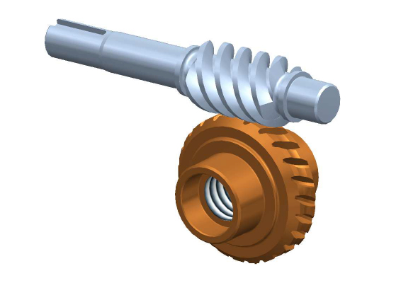
How do you calculate the gear ratio for a worm screw and gear setup?
In a worm screw and gear setup, the gear ratio is determined by the number of teeth on the worm wheel (gear) and the number of threads on the worm screw. The gear ratio represents the relationship between the rotational speed of the worm screw and the resulting rotational speed of the worm wheel. The formula to calculate the gear ratio is as follows:
Gear Ratio = Number of Teeth on Worm Wheel / Number of Threads on Worm Screw
Here’s a step-by-step process to calculate the gear ratio:
- Count the number of teeth on the worm wheel. This can be done by visually inspecting the gear or referring to its specifications.
- Count the number of threads on the worm screw. The threads refer to the number of complete turns or helical grooves wrapped around the cylindrical body of the worm screw.
- Divide the number of teeth on the worm wheel by the number of threads on the worm screw.
- The result of the division is the gear ratio. It represents the number of revolutions of the worm screw required to complete one revolution of the worm wheel.
For example, let’s say the worm wheel has 40 teeth, and the worm screw has 2 threads. Using the formula, we can calculate the gear ratio as follows:
Gear Ratio = 40 teeth / 2 threads = 20
In this case, for every full revolution of the worm screw, the worm wheel will rotate 1/20th of a revolution. This indicates a significant speed reduction, resulting in high torque output at the worm wheel.
It’s important to note that the gear ratio calculated using this formula assumes an ideal scenario without considering factors like friction, efficiency losses, or the pitch diameter of the gears. In practical applications, these factors may affect the actual gear ratio and performance of the worm screw and gear setup.


editor by CX 2024-01-19